
Wind turbine electric brake controller based on Arduino Nano:
Video how it works:
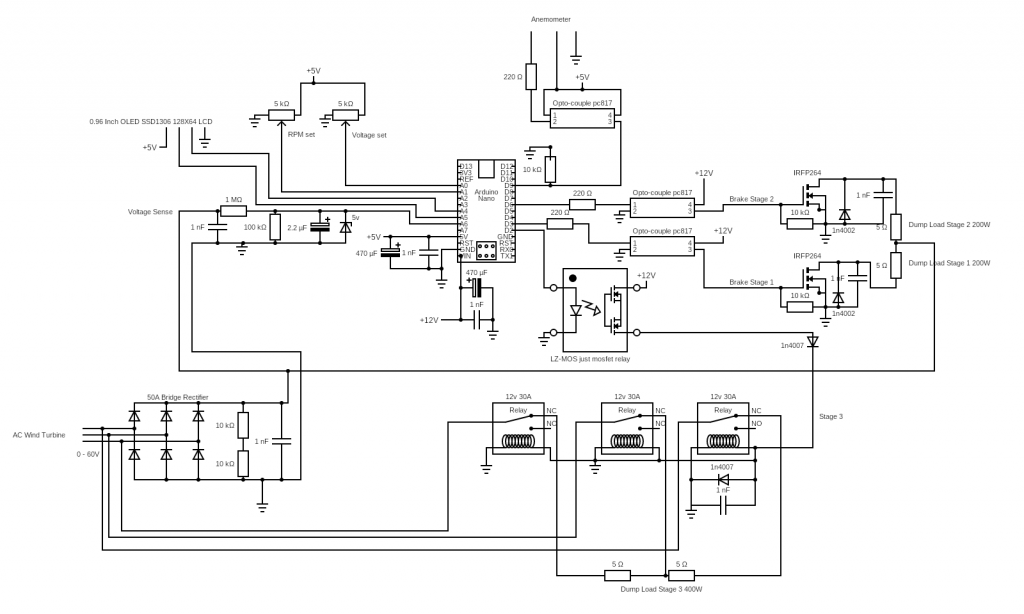
This brake controller is monitoring voltage and wind speed with custom made anemometer. Voltage limit and wind RPM limits are set by two simple potentiometers. Set limits and measured values are displayed on small OLED screen. Controller is as separate system for wind turbine brake control only, factory made Grid Tie inverter pushing generated electricity to the AC grid (it is separate system not described in this article).
Voltage monitoring has 3 stages brake logic:
- If set voltage reaching potentiometer set limit, then first mosfet is set open to dump load 5ohm powerful reostat/resistor stage 1 brake.
- If voltage from wind turbine keeps increasing stage 2 kicks in, second mosfet opens to dump load 5ohm.
- And if voltage keeps increasing stage 3 is triggered, 3x relays activate dump load 2x 5ohm on wind turbine AC 3phase line.
Wind RPM monitoring hits all 3 stages to dump load:
If wind speed reach RPM set limit, then all 3 stages dump loads gets activated. Stage 1 mosfet + Stage 2 mosfet on DC and Stage 3 relays on AC line. Full dump load is activate for 30 seconds. If within 30 seconds RPM limit hits again timer is set to 30 seconds again.
Useful feature on grid failure:
By using relays is very simple to realize wind turbine stop on grid failure, when electricity disappear due to grid maintenance or etc. wind turbine has to be stopped. Relays has NC and NO contacts, for connected dump load we use NC-(normally closed contacts). That way when controller is operating normally relays are feed with 12v DC and in case electricity from grid disappear relays closes to NC and wind turbine is connected to dump load.
Why mosfets are set to full open on brake activation, why PWM signal is not in use?
Upon lot of testing it appears that PWM on high power creates parasitic noise which makes Arduino to go crazy and crash with unknown outputs. Another thing that when using PWM mosfets were heating much more than fully open, this appears to happen due to inductance from wires kicking back to mosfets. In circuit diagram you may see many 1nF capacitors as spike filters and diodes to avoid inductance overvoltage, this was attempt to lower noise of PWM and avoid Arduino from crashing. If PWM is not in use parasitic noise.
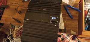
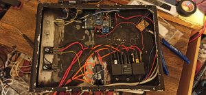
Circuit diagram and other images

Arduino Nano Code:
Failed attempt to calculate wind speed in m/s (meters per second):
Calculate anemometer circle distance (circumference)
C=2*pi*r
C - distance of anemometer circle, circumference in my case C=0.0.5969meters
pi - 3.14...
r - anemometer radius in my case r=9.5cm / 100=0.095meters
Then multiply RPS (rotations per second) with anemometer circle distance
speed=RPS*CThen multiply results with value which introduces anemometer spinning losses
speed=RPS*C*0.8NOTE: After installing controller to real wind turbine following issues came on.
- Voltage threshold between stages to low, on voltage limit all stages gets activated to fast
- One time Arduino crash/stuck, possible due to threshold between stages to low Stage 3 relays were switching fast and created high inductance noise